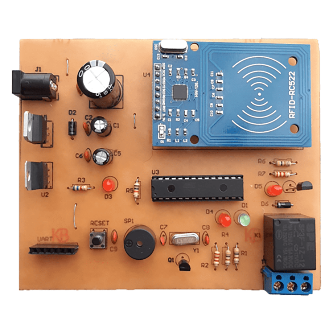
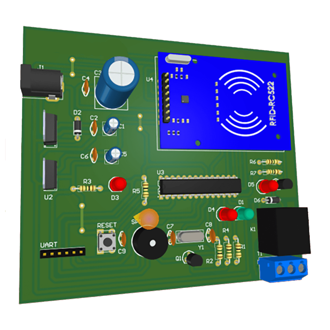
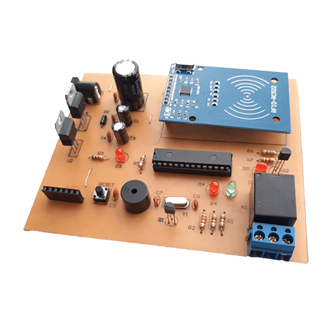
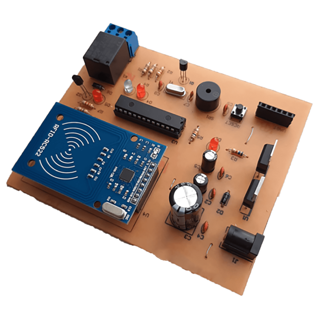
With the Digital Lock Project using the RFID RC522 module, you can connect it to an electronic lock and use an RFID card to open and close a door. This RFID door opener project can be very interesting and practical.
The operation of the RFID Door Opener with RC522 is as follows: RFID tags and cards have unique IDs, which are used by this project to identify the cards and tags. When a matching ID is detected, the relay is activated. This means that if the ID of a specific tag is stored in the project, the relay will only be activated by that tag.
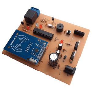
How to use the Digital Lock Project with RFID RC522 module
After building the RFID Door Opener project, you need to identify the RFID tags and cards to be used with the project. To do this, you need to obtain the ID of the tags and cards and insert them into the project code. There are two methods to obtain the ID
One of the methods is to place the RFID module on the breadboard and establish the connections between the module and Arduino based on the schematic. Then, upload the code to the Arduino and execute the Serial Monitor. Bring the tag or card close to the module. The Serial Monitor will display the ID of the tag or card. You need to take this ID and insert it into the project code, then program the Arduino. Finally, place the IC on the project.
The second method, which is simpler, is to use a USB to TTL module, such as the FT232 model. Connect this module to the project. Directly connect the project to the system via USB, and upload the code. Retrieve the ID of the tag or card from the Serial Monitor and insert it into the project code. If your USB to TTL programmer is not the FT232 model, you can connect the pins of your programmer to the header pins according to the schematic.
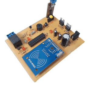
After performing the aforementioned steps, you can use the project.
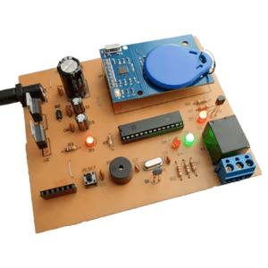
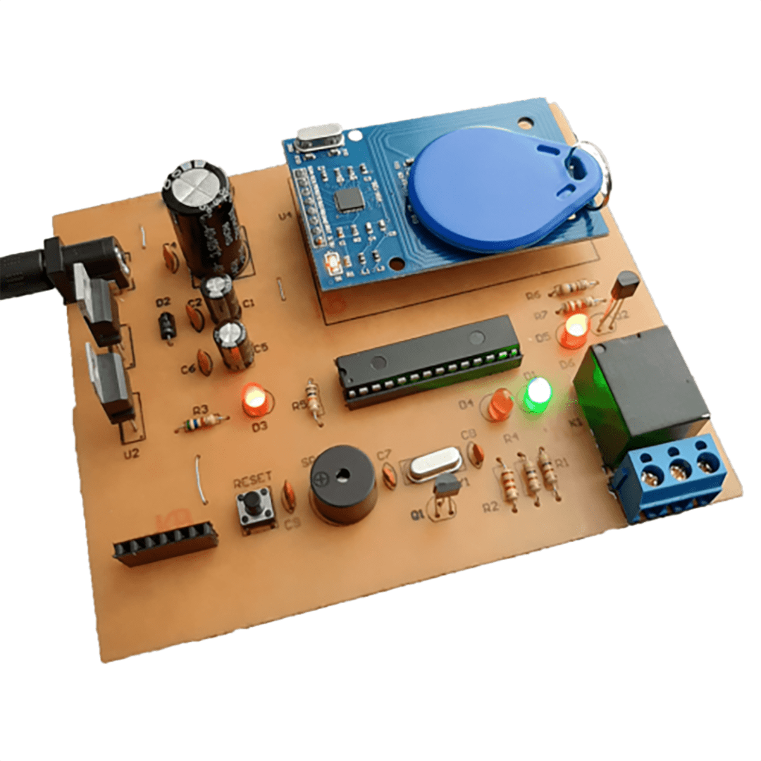
Now, by placing the assigned tag on the RFID, the relay is activated, and when the correct tag is placed on the RFID, the green LED lights up.
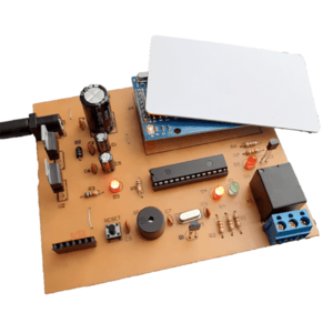
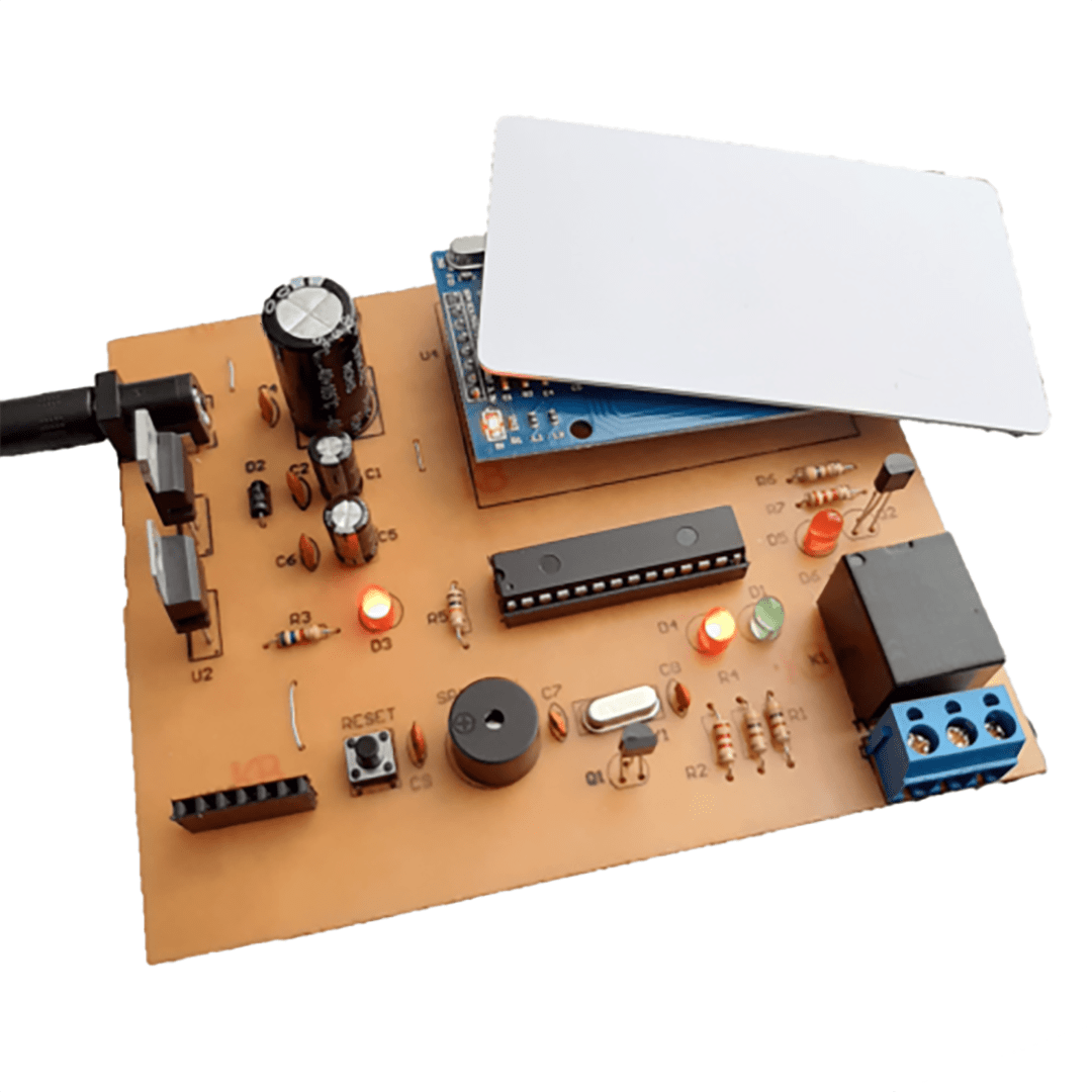
In the image below, we placed the wrong card on the project, and the red light turns on, triggering the alarm sound.
List of components used
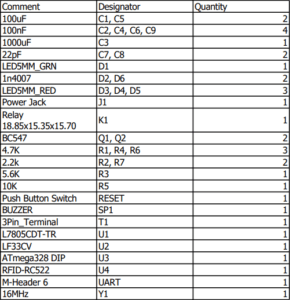
This project has:
3 months guaranteed support through ticket system
Money back guarantee in case of dissatisfaction ( according to the rules )
Free update
If you have any questions about Project, please ask in the comments section.


Comments (0)
Reviews
There are no reviews yet.