With this NRF24L01 Module Tester Project with Arduino, you can easily and quickly test NRF modules and ensure their functionality. If you test this module on a breadboard and it doesn’t work, it might be due to faulty connections or even issues with the breadboard itself. In general, it’s not recommended to test communication modules directly on a breadboard.
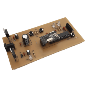
One of the modules that has gained tremendous popularity among experts in wireless communication is the NRF24L01 module. By using this module, it is possible to transmit and receive data effectively.
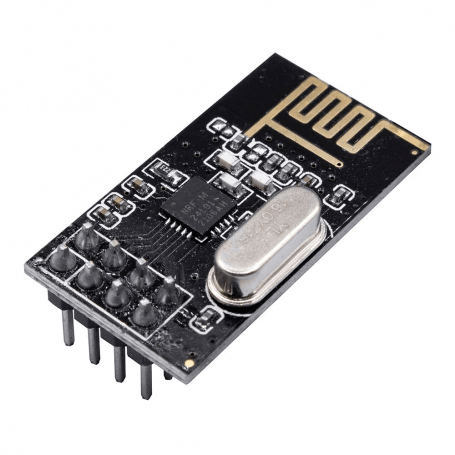
In fact, this module is a transceiver that can be configured as both a receiver and a transmitter using a microcontroller. The communication between the NRF24L01 module and the microcontroller is done through the SPI interface. There are various types of this module available in the market, each with its own specific features. However, in terms of initialization, they are all set up using the same method.
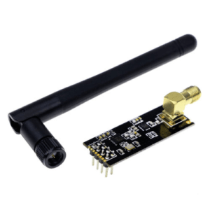
The NRF24L01 module is a transceiver module, meaning it can both transmit and receive data. This module operates at a frequency of 2.4 GHz and uses GFSK modulation. It is capable of transmitting data at a maximum speed of 2 Mbps and has a range of 100 meters in open space, or up to 1 kilometer or even more for models equipped with an external antenna.
One of the positive features of this module is its ability to create a network. Each NRF module can be connected to up to 6 other NRF modules. Therefore, the affordable price, ease of use, small dimensions, networking capability, long range, and suitable data transfer speed have made the NRF24L01 module a good choice for wireless and IoT projects.
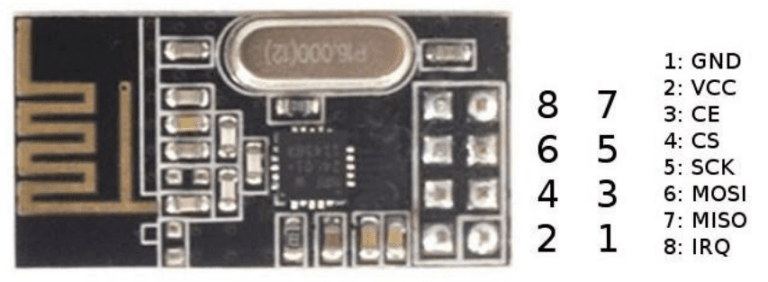
The pins of the NRF24L01 module
Pin 1: GND
Pin 2: VCC 3.3V
Pin 3: CE – Activates the SPI protocol and can be connected to one of the microcontroller pins as desired.
Pin 4: CS – Selects the module for the SPI protocol and can be connected to one of the microcontroller pins.
Pin 5: SCK – SPI synchronization pin, connected to pin 13 of Arduino or SCK of the microcontroller.
Pin 6: MOSI – SPI data transmission line, connected to pin 11 of Arduino or MOSI of the microcontroller.
Pin 7: MISO – SPI data reception line, connected to pin 12 of Arduino or MISO of the microcontroller.
Pin 8: IRQ – Interrupt pin for data reception and transmission.
How to use the NRF24L01 module tester project
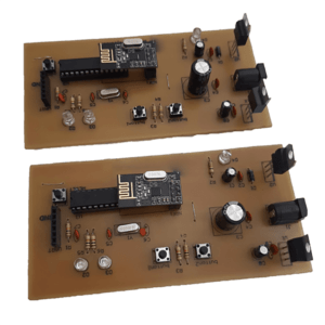
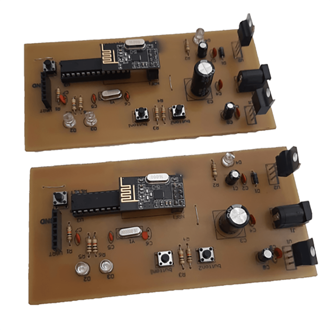
To set up the NRF module, you need to build two instances of this project so that the modules can communicate with each other, and then test them through this setup. In the project files, you will find two codes, one for the transmitter and the other for the receiver. Program each of these codes onto two separate projects. Make sure to provide voltage to the projects via an adapter to ensure proper power supply. Without it, the projects may not communicate with each other correctly.
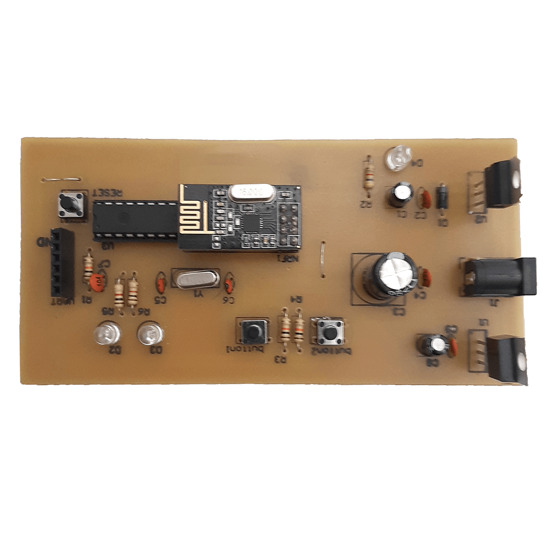
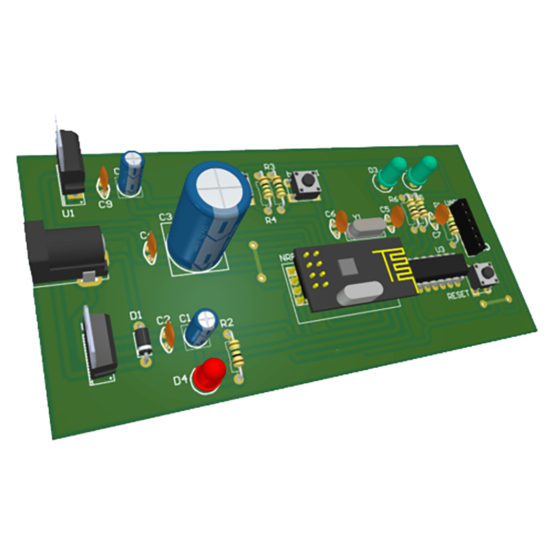
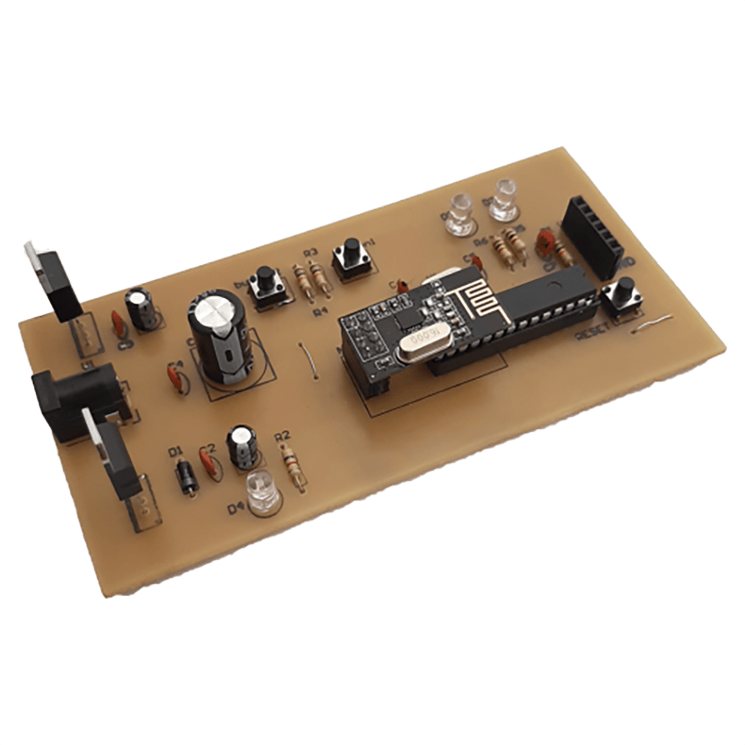
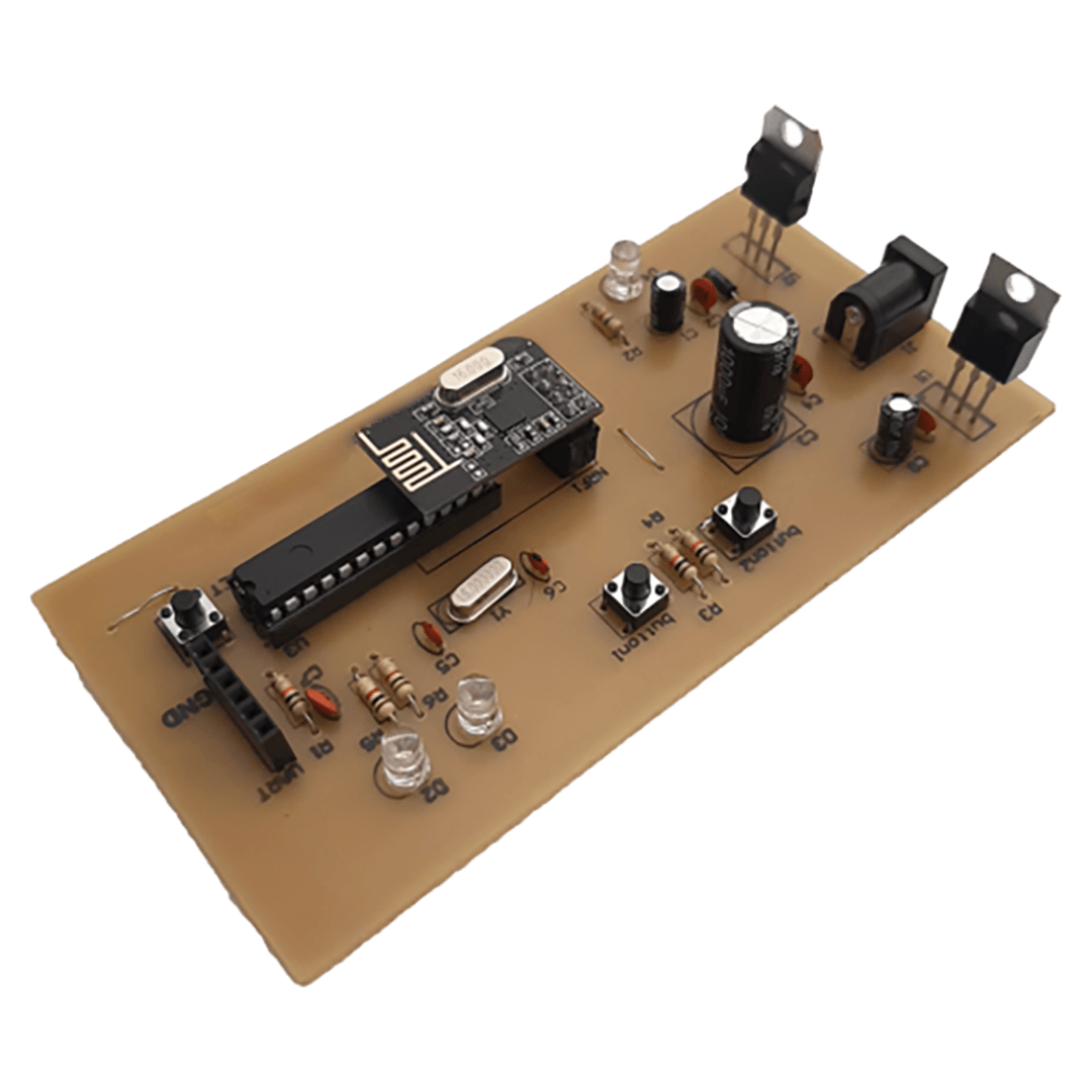
If you pay attention, you will notice that each of the projects has two microswitches and two LEDs. The reason is that in the project code, we have set up the modules to work in both transmitter and receiver modes. This means they can simultaneously send and receive data. For example, if you press the microswitch on project one, the LED on project two will turn on, and if you press the microswitch on project two, the LED on project one will turn on.
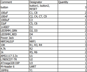
List of components used
This project has:
3 months guaranteed support through ticket system
Money back guarantee in case of dissatisfaction ( according to the rules )
Free update
If you have any questions about NRF24L01 Module Tester Project with Arduino, please ask in the comments section.


Comments (0)
Reviews
There are no reviews yet.