How to Make an 8 Microswitch Module Project , In this article, we’ll walk through the steps to create an 8-microswitch module, suitable for interfacing with any microcontroller. This project is especially useful for electronics enthusiasts who seek a reliable way to incorporate multiple microswitches into their builds without the clutter of excessive jumper wires. We’ll discuss each component, the assembly process, and a brief test setup to ensure everything works as intended.
What is an 8 Microswitch Module?
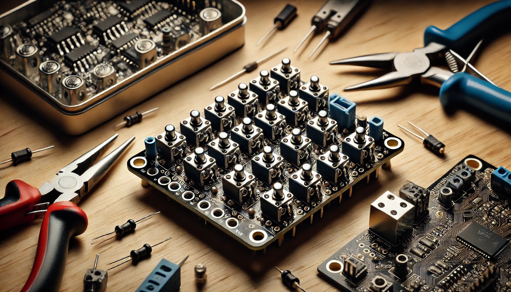
An 8-microswitch module is essentially a small circuit board that holds eight microswitches. These switches can be individually connected to a microcontroller, allowing it to detect the status (on or off) of each switch independently. Unlike using individual switches connected via breadboards and multiple jumper wires, this module offers a clean, organized, and reusable setup that integrates smoothly into various electronics projects.
Why Build a Microswitch Module?
In projects where multiple switches are needed, using individual microswitches with a breadboard can lead to instability. The switches may not fit securely, causing unreliable connections. With an 8-microswitch module, each switch is neatly housed on a PCB, reducing loose connections and simplifying the setup by providing VCC and GND pins for each switch.
Components Required
Here’s what you’ll need to build this module:
- 8 Microswitches: These are momentary contact switches that complete a circuit when pressed.
- Eight 18k Resistors: Each microswitch requires a pull-up resistor to prevent false triggering when the switch is open.
- 10-Pin Header: This header will connect the module to a microcontroller, with eight pins for the switches and two for power (VCC and GND).
- PCB (Printed Circuit Board): You can design this board or download ready-made schematics for PCB fabrication software like Altium Designer.
Step-by-Step Assembly Guide
- Soldering the Resistors:
- Begin by soldering the 18k resistors onto the PCB at the designated spots. These resistors are essential for pull-up configuration, which stabilizes the signal from each switch when it’s not pressed.
- Mounting the Microswitches:
- Place each microswitch in its respective position on the PCB. Make sure they’re oriented correctly to ensure uniform functionality. Carefully solder them in place, ensuring that all connections are secure.
- Connecting the Header Pins:
- Finally, solder the 10-pin header onto the PCB. This header will allow for easy connection to a microcontroller. Out of the 10 pins, eight are dedicated to individual microswitch outputs, while the remaining two provide power (VCC and GND).
How the 8-Microswitch Module Works
The PCB connects each microswitch to the microcontroller via the header pins. When a microswitch is pressed, it changes the output on the corresponding pin, which can then be read by the microcontroller. The VCC and GND connections are shared across all switches, making wiring and powering the module straightforward.
Testing the Module
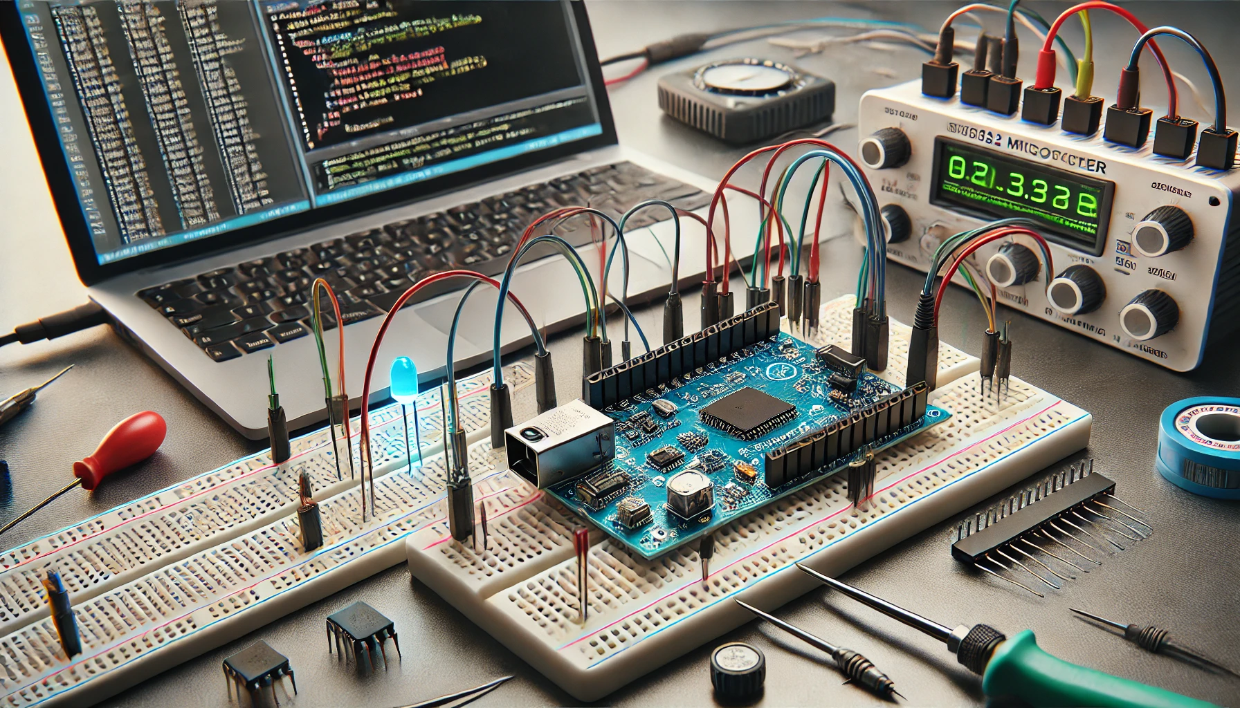
Testing is simple. Connect the module to a microcontroller and an LCD screen to display the results. Here’s a basic test setup:
- Connecting to the Microcontroller:
- Attach the 10-pin header on the module to a microcontroller’s input pins, connecting VCC and GND appropriately.
- Programming the Microcontroller:
- Write a program to read each microswitch’s state. For example, you could set up a counter that increments when one switch is pressed and decrements when another is pressed.
- Running the Test:
- When each microswitch is pressed, the counter should update accordingly on the LCD screen, verifying that each switch is functioning correctly. A helpful troubleshooting tip: if you disconnect the VCC, the module may produce erratic readings due to noise. Reconnecting VCC stabilizes the output.
Common Issues and Troubleshooting
- False Triggering: If you notice random counts without pressing any switches, check the connections and the pull-up resistors.
- Loose Connections: Verify that all solder points are solid. Loose or weak connections can lead to unreliable results.
- Power Issues: Ensure VCC is properly connected; without it, the microcontroller might receive incomplete signals.
Conclusion
Building an 8-microswitch module not only streamlines projects requiring multiple inputs but also provides a reliable interface with any microcontroller. With a tidy, reusable setup, you’ll find that integrating switches into your electronics projects is easier and more efficient than ever.
How to Make an 8 Microswitch Module Project

Video link How to Make an 8 Microswitch Module Project


Comments (0)